LSI Jiu-Jitsu

電子工作とブラジリアン柔術

モデルナワクチン

f:id:mohran:20210918013850j:image

先日、ようやく2回目のモデルナワクチンを打ちました。

これで家族全員2回打ったので少し安心です。


1回目の副反応は腕の痛みが3日ほど続いただけでしたが、モデルナの2回目はキツいと言われているので覚悟をしていました。

ワタクシ以外の家族は全員ファイザーで、2回目の副反応もほぼ無しという状況なので、家族も興味しんしん(笑)


ウソかホントか、前日からスポーツドリンクを飲めば副反応が和らぐとの噂を信じてアクエリアスを前日から4リットルほどがぶ飲みしておきました。


結果は、しばらくの間は前回同様に腕の痛みだけだったのが、接種後24時間経過した頃から強烈なダルさと吐き気、そして遂には37.8度の熱も。


接種後もアクエリアスを飲み続けていたのですけどね、無反応というわけにはいきませんでした。


倦怠感と発熱も8時間ほどで治りましたが、けっこうキツかったです。

周りのモデルナ組みは2日間寝込んだとか、39度の熱とか聞いたので、それに比べると軽かったのかもしれません。

アクエリアス効果、ということにしておこう(笑)


8ヶ月後に3回目との話も出ているけど、3回目の方が副反応がキツいとかだったら躊躇しちゃいますねぇ。

【柔術】[改] グラップリングダミー人形

1年以上ぶりの更新です。
もはやコロナに振り回され続けている1年間。
デルタ株やラムダ株など、いつまで続くのでしょうか・・。
ワクチンは1回打ちました。

柔術は、週末だけ練習へ行きながら平日はダミー人形で打ち込み練習に励む日々を続けています。
と言っても購入当初のように熱心に毎日打ち込んでいるわけでは無いですが(笑)

1年間ダミー人形を使ってみた感想としては、抑え込みやパスガード、チョーク、ベリンボロなどの打ち込みには対応できますが、スイープ系のデラヒーバや、スパイダーは厳しいと思いました。

あくまで個人的な感想ですが、試した打ち込みの効果としてはこのような感じでいます。

ハーフガード、ベリンボロ、ツイスターフック、クロスニーパス、下からの腕十字、三角締め、各種チョーク

Dハーフ、クラブライド、担ぎパス、カミツキパス

×

デラヒーバ、スパイラル、スパイダー、ラッソー、アームドラッグ、50/50


そして、ここからが本題なのですが、長い間使っていると足の強度が弱くなってしまい、そのたびに中のウエスを入れ直す作業が非常に面倒くさくて大変です。

これがウエスを詰め込んだ状態。

f:id:mohran:20210821002756j:plain:h320


何度も打ち込むと(特にベリンボロ)足の付け根がクタクタに・・。

f:id:mohran:20210821002827j:plain:h320


中のウエスが分離してしまうのでしょう。

f:id:mohran:20210821002835j:plain:w320


これをどうにかしたい、と思っていたところに100円ショップのセリアで使えそうなアイテムを見つけました。

f:id:mohran:20210821002842j:plain:w320


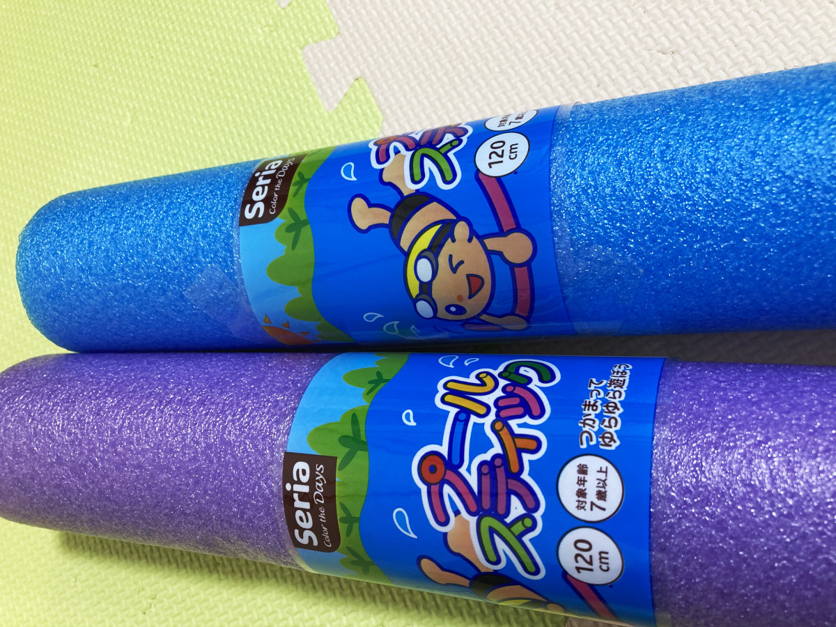
プールスティックと言う120cmの棒です。
材質はウレタンでしょうか?
これが110円で買えるのは素晴らしいと思います。

これをダミー人形の足に入れてみることにしました。

ちょっと入れにくかったですが、なんとか足から腰にかけて入りました。
(線の位置に入っています)

f:id:mohran:20210821002851j:plain:w320


この状態でしばらく使っていますが、ウエスだけの状態より圧倒的に強度の持ちが違います。
いつかはプールスティックを入れ替える日が来るかも知れませんが、そこそこ持つような気がしています。

ちなみにこのプールスティックを持って帰るのは非常に恥ずかしかったです(笑)
一旦帰って車で買いに行きました。


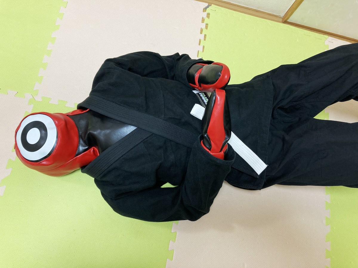
ついでにAmazonで激安道着も買って着せています。
A3を買いました。

https://www.amazon.co.jp/dp/B07GXKVJ3N/www.amazon.co.jp

f:id:mohran:20210821002900j:plain:w320


何故か帯はA2が付いていました。
ペラペラの帯で、本当にKORAL製なのかもアヤしいところです・・。

f:id:mohran:20210821002908j:plain:w320

【柔術】グラップリングダミー人形

緊急事態宣言が解除されてから3回ほど柔術の練習へ参加しました。
しかし、第2波が到来しそうな現状では、まだ自粛していた方が良いのかな?なんて葛藤する毎日です。
「え?練習行くの?」との家族からの冷ややかな目もまた痛いし(笑)

そんななか、給付金も支給されたこともあり、思い切ってグラップリングダミー人形を購入することにしました。
これがあれば自宅のジョイントマットスペースでテクニックDVDを観ながらひとり打ち込み練習ができるようになります。
ワタクシはこの類のDVDは何枚も持っていますが、まともに最後まで観たことは1度もありません。
いつも気が付くと居眠りをしており、コレクションアイテムにしかなっていないのが現状です(笑)

購入前に調べたダミー人形は、そこそこの大きさと、不気味さ(笑)もあるので予め家族に画像を見せて事前報告をしておきました。

Yahoo!ショッピングで注文し2日後には届きました。
送料込みで14,999円でした。


中身が入っていないのでシワシワですが、170cmあるのでこの時点でかなりの大きさです。


これに家族の協力のもと、古着を集めて細かく裁断して詰め込みましたが、相当大変な作業で5時間ほどかかりました。
重さはちょうど20Kgでした。


細かく裁断せずに大きめの布地のまま詰め込むと隙間ができてしまい、使っていくうちにその部分から折れ曲がってしまいました。
何度かやり直したのですが、細かい布地をギュウギュウに隙間なく詰め込むのが良い感じがします。
裁断はハサミで行っていましたが時間がかかるのでロータリーカッターを購入しました。


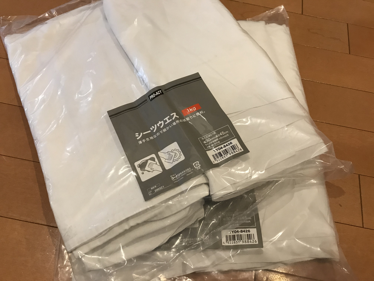
古着を全部使いきってもまだ足りなかったので、ホームセンターでウエスを買ってきました。
価格は1Kgで300円ほどでした。


ロータリーカッターを使うことで一瞬にして細かく裁断できます。


腕と足の細い部分には、棒状の物で押し込まないと入りませんでした。
クイックルワイパーの持ち手の部分を使っています(笑)


完成後、使っていないA1のキン肉マン道着を着せてみましたが小さすぎました。
A3かA4あたりがちょうど良いのかも知れません。


さっそく、最近買った加古拓渡さんのハーフガードDVDを観ながら打ち込みを開始したところ非常に良い感じでした。
やはり実際に身体を動かして練習するのは観るだけとは段違いですね。
自立はできないので立ち姿勢相手の打ち込みはできませんが、寝技の打ち込み練習には十分だと思います。
なにより人間相手では無いので気も使わなくて良いですし(笑)


しばらくは自宅練習でDVDを消化したいと思います。
最初は不気味に見えていた顔も最近は可愛く感じるようになりました(笑)

Nintendo Switchのアナログスティック交換

f:id:mohran:20200609005649j:plain

2,3か月ほど前からNintendo Switchのアナログスティックが勝手に入力されてしまうようになってしまいました。
おそらくダークソウルリマスターで酷使し過ぎたのが原因だと思われます。

だましだまし使っていたのですが、先日世界のアソビ大全を購入したところ、麻雀やトランプで隣のカードを捨ててしまったりと、大変なストレスを感じるようになったのでAmazonで工具と交換パーツのセット品を購入しました。

www.amazon.co.jp

任天堂に送って修理して貰うと1個につき2,000円かかりますので、約半分の価格で済みました。
あくまで自己責任ですが・・。

交換するにあたり、YouTubeで動画を観て自分でもできそうだなと思ったのが購入の決め手となりました。

youtu.be

youtu.be

youtu.be


いちおうカタコトの日本語のマニュアルも付属していました。
f:id:mohran:20200609005832j:plain

工具は必要十分なほど付属しています。
f:id:mohran:20200609005847j:plain

アナログスティックの質感もほぼ同じ感触でした。
f:id:mohran:20200609005909j:plain

左コントローラーを開けてバッテリーを外します。
f:id:mohran:20200609005918j:plain

バッテリーは両面テープで接着されているのでプラスチック工具を使って外します。
f:id:mohran:20200609005929j:plain

バッテリー受けのカバーを外すとアナログスティックを取り外せます。
フラットケーブルの爪はピンセットを使って持ち上げます。
f:id:mohran:20200609005940j:plain

交換後、戻す際にバッテリーのコネクタは、上から押し付けて差し込みます。
f:id:mohran:20200609005951j:plain

右コントローラーはネジ位置が異なっています。
f:id:mohran:20200609010044j:plain

アナログスティックは、こちらの方が外しやすかったです。
f:id:mohran:20200609010053j:plain

交換後はスティック補正で問題無いことを確認しました。
f:id:mohran:20200609010102j:plain

作業時間は1つ10分ほどでした。

2,3年後にも再度交換することになるかも知れませんし、バッテリーやボタン交換などもできるようになりましたので、レベルが1つ上がった気分です。

RGB OLEDで遊ぶ (2) - PPMファイル表示

f:id:mohran:20200521235152j:plain

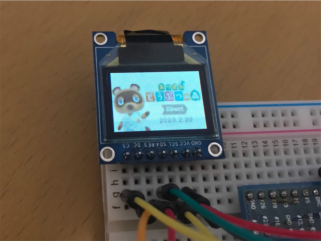
Raspberry PiからPPMファイルを表示するプログラムを組んでみました。

こちらの記事のPBMファイル作成と同じようにGIMPで96x64へリサイズして、PPMフォーマットへエクスポートします。

f:id:mohran:20200521235247j:plain

f:id:mohran:20200521235256j:plain

プログラムはこのような感じです。


コンパイルを行い実行時の引数にPPMファイルを指定します。

$ gcc spi.c -lwiringPi

$ ./a.out xxxx.ppm


なお、PPMファイルはGIMPからエクスポートしたフォーマットを対象にしているので、それ以外のフォーマットでは正しく表示できないと思いますのでご了承ください。

f:id:mohran:20200521235316j:plain


[参考記事]

RGB OLEDで遊ぶ (1) - SSD1331

f:id:mohran:20200520212031j:plain

秋月電子で購入したRGB-OLEDをRaspberry Piから動かして遊んでみました。
コントローラーであるSSD1331のライブラリが公開されていますが、コマンドを直接叩いて動かしてみたので纏めてみます。

http://akizukidenshi.com/catalog/g/gP-14435/
akizukidenshi.com

データシートは上記の商品ページからダウンロードしました。
f:id:mohran:20200520212252j:plain

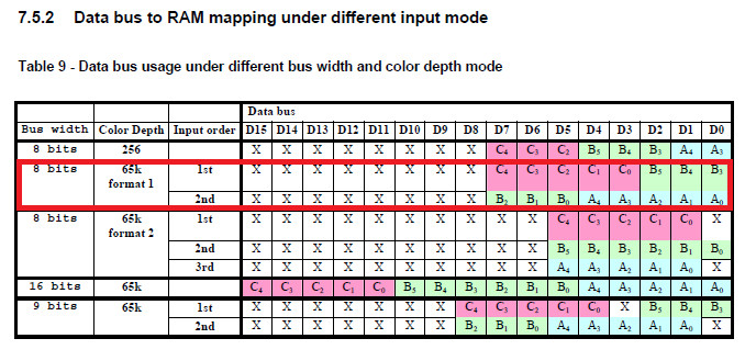
以前調べたSSD1306と同じように、座標を指定した後にデータを送信することで表示が行われますがデータは1画素につき1~2Byteとなっています。
データのフォーマットは0xa0番地のbit[7:6]で指定しますが、設定値1の65K format1で行いました。
f:id:mohran:20200520212457j:plain

1Byte目がR-5bitとG-上位3bit、2Byte目がG-下位3bitとB-5bitの2Byte構成になっています。
図中のCBAがRGBに対応しており、0xa0番地の[2]=1で反転してCBA=BGRにすることもできます。

8章からコマンドが記載されています。
コマンドはたくさんありますが、理解できたコマンドのみ記載します(笑)

f:id:mohran:20200520213230j:plain

表示する座標の設定
  • 0x15 : Set Column Address
  • 0x75 : Set Row Address
wd[0] = 0x15;
wd[1] = 0;   // Column Address of Start 0-95
wd[2] = 95;  // Column Address of End 0-95
wiringPiSPIwdRW(SPI_CHANNEL, wd, 3);

wd[0] = 0x75;
wd[1] = 0;   // Row Address of Start 0-63
wd[2] = 63;  // Row Address of End 0-63
wiringPiSPIDataRW(SPI_CHANNEL, wd, 3);


データフォーマット、パネルの設定
  • 0xa0 : Remap & Color Depth setting
wd[0] = 0xa0;
wd[1] = 0x60;  // [7:6] = 0x1 : 65k color format
               // [5]   = 0x1 : Enable COM Split Odd Even
               // [4]   = 0x0 : Scan from COM 0 to COM [N-1]
               // [3]   = 0x0 : Disable left-right swapping on COM
               // [2]   = 0x0 : normal order RGB
               // [1]   = 0x0 : RAM Column 0 to 95 maps to Pin Seg 0 to 95
               // [0]   = 0x0 : Horizontal address increment
wiringPiSPIDataRW(SPI_CHANNEL, wd, 2);


// 左右反転
wd[0] = 0xa0;
wd[1] = 0x62;  // [7:6] = 0x1 : 65k color format
               // [5]   = 0x1 : Enable COM Split Odd Even
               // [4]   = 0x0 : Scan from COM0 to COM[N-1]
               // [3]   = 0x0 : Disable left-right swapping on COM
               // [2]   = 0x0 : normal order RGB
               // [1]   = 0x1 : RAM Column 0 to 95 maps to Pin Seg 95 to 0
               // [0]   = 0x0 : Horizontal address increment
wiringPiSPIDataRW(SPI_CHANNEL, wd, 2);


// 上下左右反転(シルク印刷と同じ向きになる)
wd[0] = 0xa0;
wd[1] = 0x72;  // [7:6] = 0x1 : 65k color format
               // [5]   = 0x1 : Enable COM Split Odd Even
               // [4]   = 0x1 : Scan from COM[N-1] to COM0
               // [3]   = 0x0 : Disable left-right swapping on COM
               // [2]   = 0x0 : normal order RGB
               // [1]   = 0x1 : RAM Column 0 to 95 maps to Pin Seg 95 to 0
               // [0]   = 0x0 : Horizontal address increment
wiringPiSPIDataRW(SPI_CHANNEL, wd, 2);
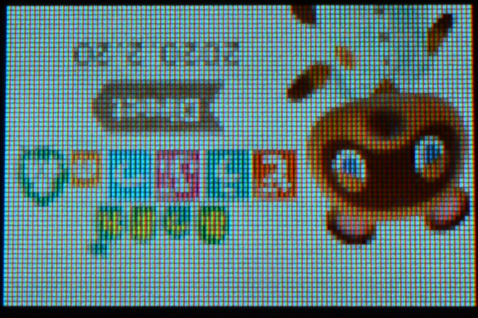


各色のコントラスト設定
  • 0x81 : Set Contrast for Color "A"
  • 0x82 : Set Contrast for Color "B"
  • 0x83 : Set Contrast for Color "C"
wd[0] = 0x81;
wd[1] = 255;  // A Contrast 0-255
wd[2] = 0x82;
wd[3] = 0;    // B Contrast 0-255
wd[4] = 0x83;
wd[5] = 0;    // C Contrast 0-255
wiringPiSPIDataRW(SPI_CHANNEL, wd, 6);


wd[0] = 0x81;
wd[1] = 0;    // A Contrast 0-255
wd[2] = 0x82;
wd[3] = 255;  // B Contrast 0-255
wd[4] = 0x83;
wd[5] = 0;    // C Contrast 0-255
wiringPiSPIDataRW(SPI_CHANNEL, wd, 6);
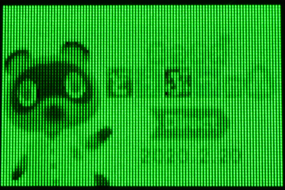

wd[0] = 0x81;
wd[1] = 0;    // A Contrast 0-255
wd[2] = 0x82;
wd[3] = 0;    // B Contrast 0-255
wd[4] = 0x83;
wd[5] = 255;  // C Contrast 0-255
wiringPiSPIDataRW(SPI_CHANNEL, wd, 6);
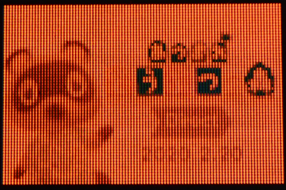


パネルに供給する電流値の設定
  • 0x87 : Master Current Control
// 値が小さいほど暗くなる
wd[0] = 0x87;
wd[1] = 0;  // 0-15
wiringPiSPIDataRW(SPI_CHANNEL, wd, 2);


表示モード
  • 0xa4 ~ 0xa7 : Set Display Mode

0xa4 : 通常表示
0xa5 : 全表示

wd[0] = 0xa5;
wiringPiSPIDataRW(SPI_CHANNEL, wd, 1);

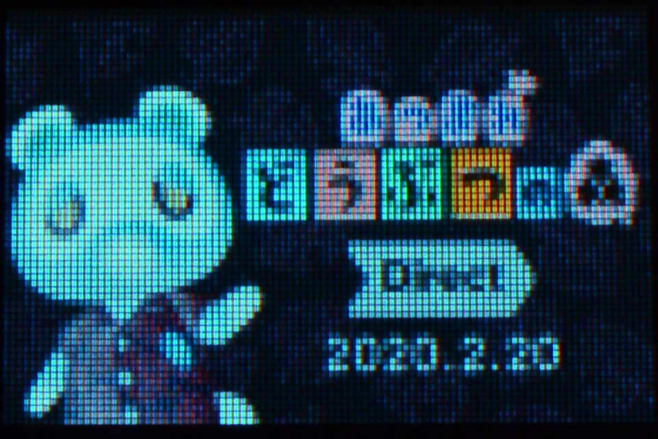
0xa6 : 表示OFF
0xa7 : 色反転表示

wd[0] = 0xa7;
wiringPiSPIDataRW(SPI_CHANNEL, wd, 1);


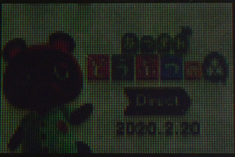
調光モード設定
  • 0xab : Dim Mode Setting
wd[0] = 0xab;
wd[1] = 0x00;  // Reserved
wd[2] = 10;    // A Contrast 0-255
wd[3] = 10;    // B Contrast 0-255
wd[4] = 10;    // C Contrast 0-255
wd[5] = 10;    // Precharge voltage setting 0-31
wiringPiSPIDataRW(SPI_CHANNEL, wd, 6);

wd[0] = 0xac;  // dim mode
wiringPiSPIDataRW(SPI_CHANNEL, wd, 1);


表示On/Off
  • 0xac ~ 0xa7 : Set Display ON/OFF

0xac : Display ON in dim mode
0xae : Display OFF (sleep mode)
0xaf : Display ON in normal mode

調光ウィンドウ設定(画面内の一部分のみ調光)
  • 0x24 : Dim Window
wd[0] = 0x24;
wd[1] = 10;  // Column Address of Start 0-95
wd[2] = 10;  // Row Address of Start 0-63
wd[3] = 85;  // Column Address of End 0-95
wd[4] = 53;  // Row Address of End 0-63
wiringPiSPIDataRW(SPI_CHANNEL, wd, 5);
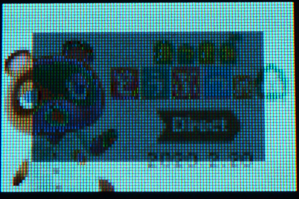


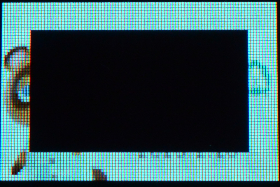
クリアウィンドウ設定(画面内の一部分のみクリア)
  • 0x25 : Clear Window
wd[0] = 0x25;
wd[1] = 10;  // Column Address of Start 0-95
wd[2] = 10;  // Row Address of Start 0-63
wd[3] = 85;  // Column Address of End 0-95
wd[4] = 53;  // Row Address of End 0-63
wiringPiSPIDataRW(SPI_CHANNEL, wd, 5);

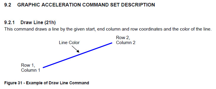
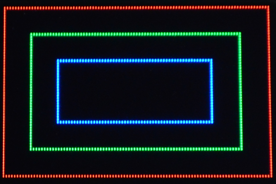
直線と四角形を表示するコマンドが予め用意されています。
f:id:mohran:20200520220402j:plain

直線表示
  • 0x21 : Draw Line
// 赤
wd[0] = 0x21;
wd[1] = 0;     // Column Address of Start 0-95
wd[2] = 15;    // Row Address of Start 0-63
wd[3] = 75;    // Column Address of End 0-95
wd[4] = 63;    // Row Address of End 0-63
wd[5] = 0x3e;  // Color C of the line 0x00-0x3e([0]=0)
wd[6] = 0x00;  // Color B of the line 0x00-0x3f
wd[7] = 0x00;  // Color A of the line 0x00-0x3e([0]=0)
wiringPiSPIDataRW(SPI_CHANNEL, wd, 8);
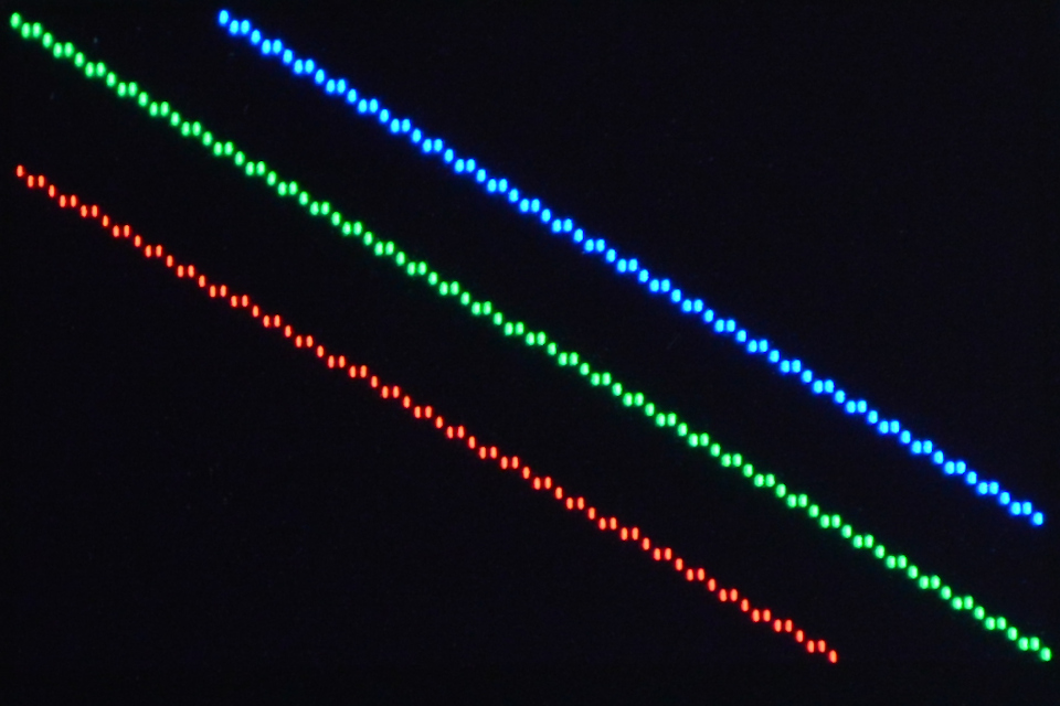
// 緑
wd[0] = 0x21;
wd[1] = 0;     // Column Address of Start 0-95
wd[2] = 0;     // Row Address of Start 0-63
wd[3] = 95;    // Column Address of End 0-95
wd[4] = 63;    // Row Address of End 0-63
wd[5] = 0x00;  // Color C of the line 0x00-0x3e([0]=0)
wd[6] = 0x3f;  // Color B of the line 0x00-0x3f
wd[7] = 0x00;  // Color A of the line 0x00-0x3e([0]=0)
wiringPiSPIDataRW(SPI_CHANNEL, wd, 8);

// 青
wd[0] = 0x21;
wd[1] = 20;    // Column Address of Start 0-95
wd[2] = 0;     // Row Address of Start 0-63
wd[3] = 95;    // Column Address of End 0-95
wd[4] = 50;    // Row Address of End 0-63
wd[5] = 0x00;  // Color C of the line 0x00-0x3e([0]=0)
wd[6] = 0x00;  // Color B of the line 0x00-0x3f
wd[7] = 0x3e;  // Color A of the line 0x00-0x3e([0]=0)
wiringPiSPIDataRW(SPI_CHANNEL, wd, 8);


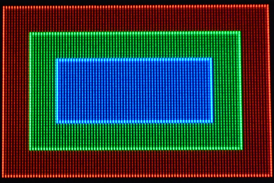
四角形表示と塗りつぶし
  • 0x22 : Drawing Rectangle
  • 0x26 : Fill Enable / Disable
// 塗りつぶし無し
wd[0] = 0x26;
wd[1] = 0x00;  // [4] = 0x0 : Disable reverse copy
               // [0] = 0x0 : Disable Fill for Draw Rectangle
wiringPiSPIDataRW(SPI_CHANNEL, wd, 2);

// 赤
wd[0]  = 0x22;
wd[1]  = 0;     // Column Address of Start 0-95
wd[2]  = 0;     // Row Address of Start 0-63
wd[3]  = 95;    // Column Address of End 0-95
wd[4]  = 63;    // Row Address of End 0-63
wd[5]  = 0x3e;  // Color C of the line 0x00-0x3e([0]=0)
wd[6]  = 0x00;  // Color B of the line 0x00-0x3f
wd[7]  = 0x00;  // Color A of the line 0x00-0x3e([0]=0)
wd[8]  = 0x00;  // Color C of the fill area 0x00-0x3e([0]=0)
wd[9]  = 0x00;  // Color B of the fill area 0x00-0x3f
wd[10] = 0x00;  // Color A of the fill area 0x00-0x3e([0]=0)
wiringPiSPIDataRW(SPI_CHANNEL, wd, 11);
// 緑
wd[0]  = 0x22;
wd[1]  = 10;    // Column Address of Start 0-95
wd[2]  = 10;    // Row Address of Start 0-63
wd[3]  = 85;    // Column Address of End 0-95
wd[4]  = 53;    // Row Address of End 0-63
wd[5]  = 0x00;  // Color C of the line 0x00-0x3e([0]=0)
wd[6]  = 0x3f;  // Color B of the line 0x00-0x3f
wd[7]  = 0x00;  // Color A of the line 0x00-0x3e([0]=0)
wd[8]  = 0x00;  // Color C of the fill area 0x00-0x3e([0]=0)
wd[9]  = 0x00;  // Color B of the fill area 0x00-0x3f
wd[10] = 0x00;  // Color A of the fill area 0x00-0x3e([0]=0)
wiringPiSPIDataRW(SPI_CHANNEL, wd, 11);
// 青
wd[0]  = 0x22;
wd[1]  = 20;    // Column Address of Start 0-95
wd[2]  = 20;    // Row Address of Start 0-63
wd[3]  = 75;    // Column Address of End 0-95
wd[4]  = 43;    // Row Address of End 0-63
wd[5]  = 0x00;  // Color C of the line 0x00-0x3e([0]=0)
wd[6]  = 0x00;  // Color B of the line 0x00-0x3f
wd[7]  = 0x3e;  // Color A of the line 0x00-0x3e([0]=0)
wd[8]  = 0x00;  // Color C of the fill area 0x00-0x3e([0]=0)
wd[9]  = 0x00;  // Color B of the fill area 0x00-0x3f
wd[10] = 0x00;  // Color A of the fill area 0x00-0x3e([0]=0)
wiringPiSPIDataRW(SPI_CHANNEL, wd, 11);


// 塗りつぶし有り
wd[0] = 0x26;
wd[1] = 0x01;  // [4] = 0x0 : Disable reverse copy
               // [0] = 0x1 : Enable Fill for Draw Rectangle
wiringPiSPIDataRW(SPI_CHANNEL, wd, 2);

// 赤
wd[0]  = 0x22;
wd[1]  = 0;     // Column Address of Start 0-95
wd[2]  = 0;     // Row Address of Start 0-63
wd[3]  = 95;    // Column Address of End 0-95
wd[4]  = 63;    // Row Address of End 0-63
wd[5]  = 0x3e;  // Color C of the line 0x00-0x3e([0]=0)
wd[6]  = 0x00;  // Color B of the line 0x00-0x3f
wd[7]  = 0x00;  // Color A of the line 0x00-0x3e([0]=0)
wd[8]  = 0x0e;  // Color C of the fill area 0x00-0x3e([0]=0)
wd[9]  = 0x00;  // Color B of the fill area 0x00-0x3f
wd[10] = 0x00;  // Color A of the fill area 0x00-0x3e([0]=0)
wiringPiSPIDataRW(SPI_CHANNEL, wd, 11);

// 緑
wd[0]  = 0x22;
wd[1]  = 10;    // Column Address of Start 0-95
wd[2]  = 10;    // Row Address of Start 0-63
wd[3]  = 85;    // Column Address of End 0-95
wd[4]  = 53;    // Row Address of End 0-63
wd[5]  = 0x00;  // Color C of the line 0x00-0x3e([0]=0)
wd[6]  = 0x3f;  // Color B of the line 0x00-0x3f
wd[7]  = 0x00;  // Color A of the line 0x00-0x3e([0]=0)
wd[8]  = 0x00;  // Color C of the fill area 0x00-0x3e([0]=0)
wd[9]  = 0x0f;  // Color B of the fill area 0x00-0x3f
wd[10] = 0x00;  // Color A of the fill area 0x00-0x3e([0]=0)
wiringPiSPIDataRW(SPI_CHANNEL, wd, 11);

// 青
wd[0]  = 0x22;
wd[1]  = 20;    // Column Address of Start 0-95
wd[2]  = 20;    // Row Address of Start 0-63
wd[3]  = 75;    // Column Address of End 0-95
wd[4]  = 43;    // Row Address of End 0-63
wd[5]  = 0x00;  // Color C of the line 0x00-0x3e([0]=0)
wd[6]  = 0x00;  // Color B of the line 0x00-0x3f
wd[7]  = 0x3e;  // Color A of the line 0x00-0x3e([0]=0)
wd[8]  = 0x00;  // Color C of the fill area 0x00-0x3e([0]=0)
wd[9]  = 0x00;  // Color B of the fill area 0x00-0x3f
wd[10] = 0x0e;  // Color A of the fill area 0x00-0x3e([0]=0)
wiringPiSPIDataRW(SPI_CHANNEL, wd, 11);


コピー
  • 0x23 : Copy
// 通常コピー
wd[0] = 0x26;
wd[1] = 0x00;  // [4] : Disable reverse copy
               // [0] : Disable Fill for Draw Rectangle
wiringPiSPIDataRW(SPI_CHANNEL, wd, 2);

wd[0] = 0x23;
wd[1] = 0;   // Column Address of Start 0-95
wd[2] = 0;   // Row Address of Start 0-63
wd[3] = 40;  // Column Address of End 0-95
wd[4] = 40;  // Row Address of End 0-63
wd[5] = 50;  // Column Address of New Start 0-95
wd[6] = 15;  // Row Address of New Start 0-63
wiringPiSPIDataRW(SPI_CHANNEL, wd, 7);


// 色反転コピー
wd[0] = 0x26;
wd[1] = 0x10;  // [4] : Enable reverse during copy
               // [0] : Disable Fill for Draw Rectangle
wiringPiSPIDataRW(SPI_CHANNEL, wd, 2);

wd[0] = 0x23;
wd[1] = 0;   // Column Address of Start 0-95
wd[2] = 0;   // Row Address of Start 0-63
wd[3] = 40;  // Column Address of End 0-95
wd[4] = 40;  // Row Address of End 0-63
wd[5] = 50;  // Column Address of New Start 0-95
wd[6] = 15;  // Row Address of New Start 0-63
wiringPiSPIDataRW(SPI_CHANNEL, wd, 7);


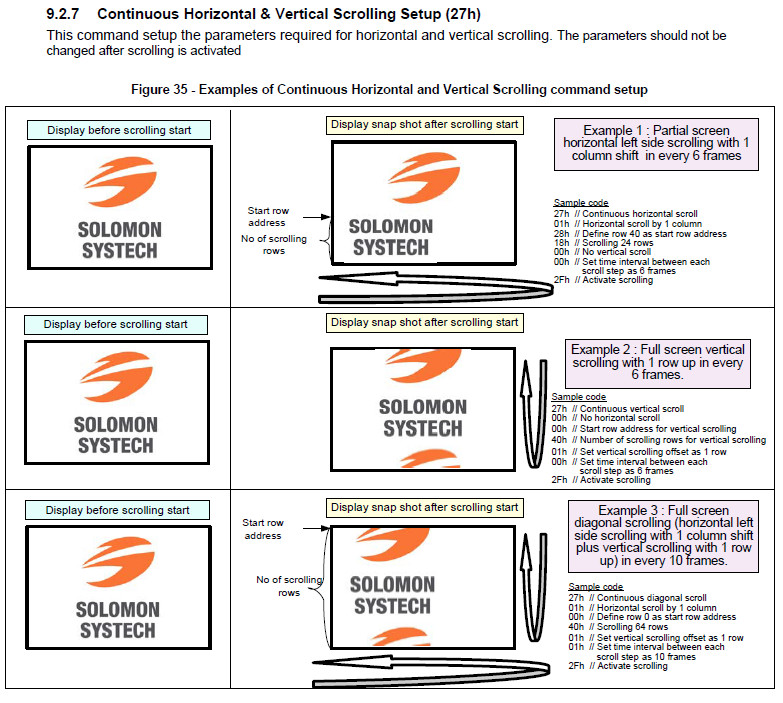
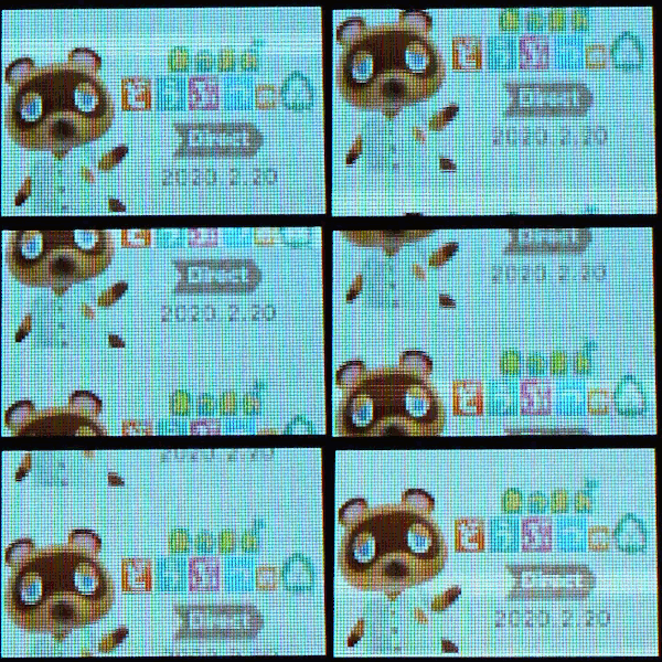
スクロール設定
  • 0x27 : Continuous Horizontal & Vertical Scrolling Setup
  • 0x2e : Deactivate scrolling
  • 0x2f : Activate scrolling

データシートに記載されているサンプル設定で動かしてみました。
f:id:mohran:20200520222453j:plain

// Example 1
wd[0] = 0x27;
wd[1] = 0x01;  // Set number of column as horizontal scroll offset 0-95
wd[2] = 0x28;  // Define start row address 0-63
wd[3] = 0x18;  // Set number of rows to be horizontal scrolled 0-64
wd[4] = 0x00;  // Set number of row as vertical scroll offset0-63
wd[5] = 0x00;  // Set time interval between each scroll step 0-3
wiringPiSPIDataRW(SPI_CHANNEL, wd, 6);

wd[0] = 0x2f;  // Activate scrolling
wiringPiSPIDataRW(SPI_CHANNEL, wd, 1);

f:id:mohran:20200520222625g:plain

// Example 2
wd[0] = 0x27;
wd[1] = 0x00;  // Set number of column as horizontal scroll offset 0-95
wd[2] = 0x00;  // Define start row address 0-63
wd[3] = 0x40;  // Set number of rows to be horizontal scrolled 0-64
wd[4] = 0x01;  // Set number of row as vertical scroll offset0-63
wd[5] = 0x00;  // Set time interval between each scroll step 0-3
wiringPiSPIDataRW(SPI_CHANNEL, wd, 6);

wd[0] = 0x2f;  // Activate scrolling
wiringPiSPIDataRW(SPI_CHANNEL, wd, 1);
f:id:mohran:20200520222659g:plain

// Example 3
wd[0] = 0x27;
wd[1] = 0x01;  // Set number of column as horizontal scroll offset 0-95
wd[2] = 0x00;  // Define start row address 0-63
wd[3] = 0x40;  // Set number of rows to be horizontal scrolled 0-64
wd[4] = 0x01;  // Set number of row as vertical scroll offset0-63
wd[5] = 0x01;  // Set time interval between each scroll step 0-3
wiringPiSPIDataRW(SPI_CHANNEL, wd, 6);

wd[0] = 0x2f;  // Activate scrolling
wiringPiSPIDataRW(SPI_CHANNEL, wd, 1);
f:id:mohran:20200520222728g:plain


[参考記事]

Raspberry PiでSPI

f:id:mohran:20200515004533j:plain
Raspberry PiでSPI接続のOLEDを動かしてみましたので備忘録です。

C言語を通して制御しましたのでライブラリのWiring Piをインストールしておきます。

$ sudo apt-get install wiringpi


一般的なSPI接続のOLEDは、「GND」「VCC」の他にSPI通信用の「SCL」「SDA」「CS」と「RES(リセット)」「DC(データ/コマンド)」の7ピン構成になっています。

Wiring Piを使うことでSPI通信用の3本は自動で制御してくれますが、「RES」と「DC」は手動でポートを制御する必要があります。
f:id:mohran:20200516224143j:plain

gpioコマンドでポートの位置を確認できます。

$ gpio readall


SPIのピンは固定ですが、「RES」と「DC」は空きポートを使用しました。

f:id:mohran:20200516225429j:plain

C言語の記述はこのような感じです。

  • SPI通信
#include <wiringPiSPI.h>

#define SPI_CHANNEL 0
#define SPI_SPEED   1000000

if(wiringPiSPISetup(SPI_CHANNEL, SPI_SPEED) < 0){
  return(-1);
}

wd[0] = 0xaf;
wd[1] = 0x15;
wd[2] = 0x60;
wiringPiSPIDataRW(SPI_CHANNEL, wd, 3);

wiringPiSPISetupの第2引数はSPIクロック周波数を指定します。
(今回は1MHz)
wiringPiSPIDataRWの第2引数は送信するデータ配列で、第3引数は送信データ長となります。

  • ポート制御
#include <wiringPi.h>

#define PORT_RES 20
#define PORT_DC  21

if(wiringPiSetupGpio() < 0){
  return(-1);
}

pinMode(PORT_RES, OUTPUT);
pinMode(PORT_DC,  OUTPUT);

digitalWrite(PORT_RES, 1);
digitalWrite(PORT_DC,  0);

pinMode第1引数で指定するポート番号はgpio readallで表示されるBCM欄の番号になります。
なお、入力ポートの状態をリードするにはこのようになります。

pinMode(xx, INPUT);
rd = digitalRead(xx);


コンパイルする際にはWiring Piのライブラリをリンクさせる必要があります。

$ gcc spi.c -lwiringPi


SPIクロックの速度を500KHzと1MHzで観測してみたところ、設定通りの速度でした。
f:id:mohran:20200515015645j:plain

f:id:mohran:20200515015659j:plain


[参考記事]