RGB OLEDで遊ぶ (1) - SSD1331
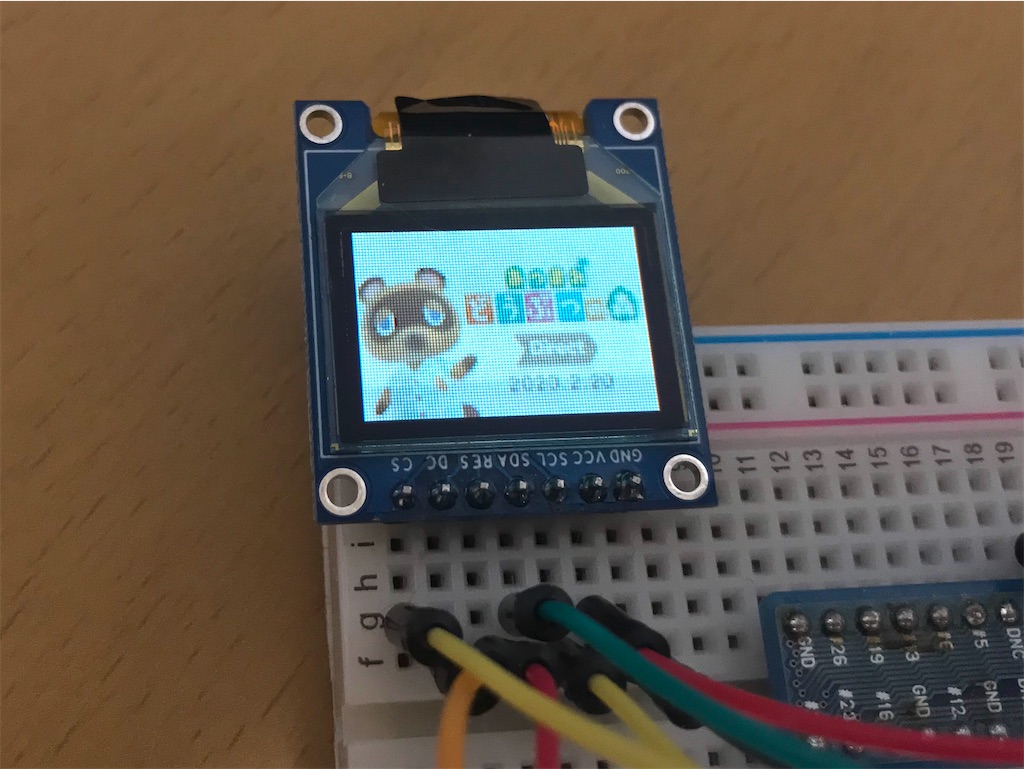
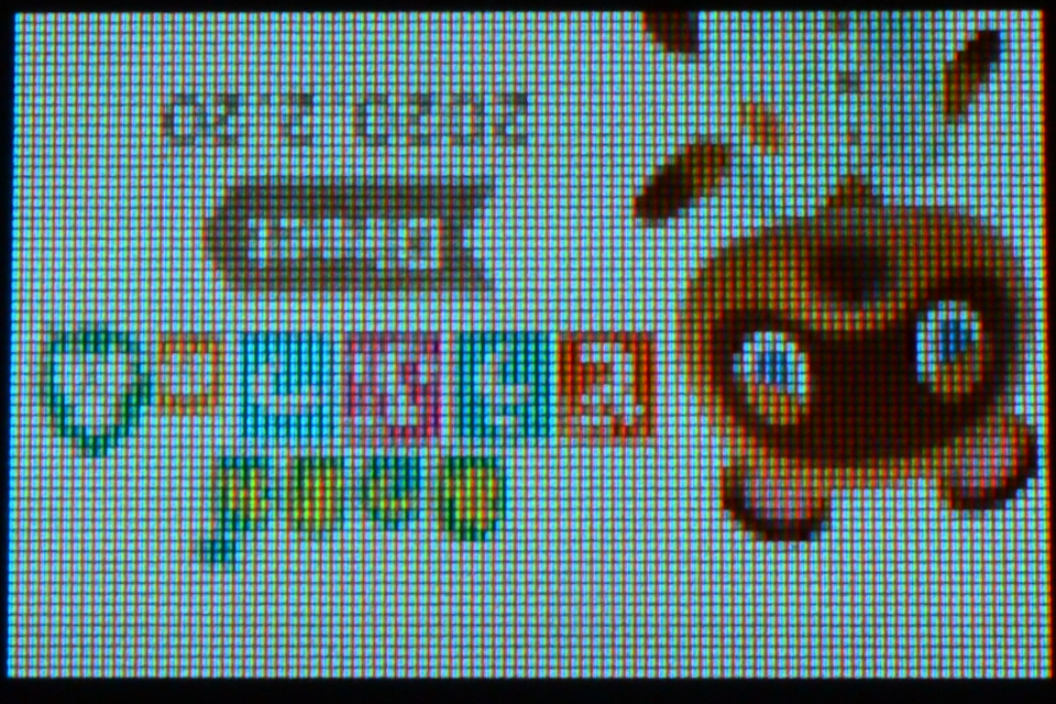
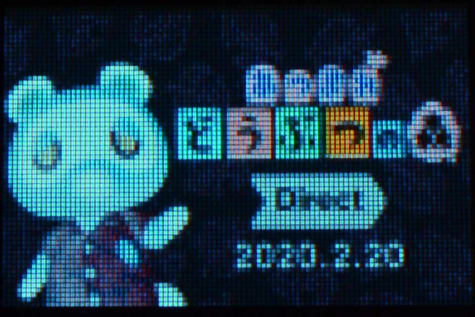
秋月電子で購入したRGB-OLEDをRaspberry Piから動かして遊んでみました。
コントローラーであるSSD1331のライブラリが公開されていますが、コマンドを直接叩いて動かしてみたので纏めてみます。
http://akizukidenshi.com/catalog/g/gP-14435/
akizukidenshi.com
データシートは上記の商品ページからダウンロードしました。
以前調べたSSD1306と同じように、座標を指定した後にデータを送信することで表示が行われますがデータは1画素につき1~2Byteとなっています。
データのフォーマットは0xa0番地のbit[7:6]で指定しますが、設定値1の65K format1で行いました。
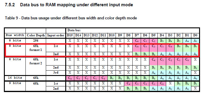
1Byte目がR-5bitとG-上位3bit、2Byte目がG-下位3bitとB-5bitの2Byte構成になっています。
図中のCBAがRGBに対応しており、0xa0番地の[2]=1で反転してCBA=BGRにすることもできます。
8章からコマンドが記載されています。
コマンドはたくさんありますが、理解できたコマンドのみ記載します(笑)

表示する座標の設定
- 0x15 : Set Column Address
- 0x75 : Set Row Address
wd[0] = 0x15;
wd[1] = 0;   // Column Address of Start 0-95
wd[2] = 95;  // Column Address of End 0-95
wiringPiSPIwdRW(SPI_CHANNEL, wd, 3);

wd[0] = 0x75;
wd[1] = 0;   // Row Address of Start 0-63
wd[2] = 63;  // Row Address of End 0-63
wiringPiSPIDataRW(SPI_CHANNEL, wd, 3);
データフォーマット、パネルの設定
- 0xa0 : Remap & Color Depth setting
wd[0] = 0xa0;
wd[1] = 0x60;  // [7:6] = 0x1 : 65k color format
               // [5]   = 0x1 : Enable COM Split Odd Even
               // [4]   = 0x0 : Scan from COM 0 to COM [N-1]
               // [3]   = 0x0 : Disable left-right swapping on COM
               // [2]   = 0x0 : normal order RGB
               // [1]   = 0x0 : RAM Column 0 to 95 maps to Pin Seg 0 to 95
               // [0]   = 0x0 : Horizontal address increment
wiringPiSPIDataRW(SPI_CHANNEL, wd, 2);
// 左右反転
wd[0] = 0xa0;
wd[1] = 0x62;  // [7:6] = 0x1 : 65k color format
               // [5]   = 0x1 : Enable COM Split Odd Even
               // [4]   = 0x0 : Scan from COM0 to COM[N-1]
               // [3]   = 0x0 : Disable left-right swapping on COM
               // [2]   = 0x0 : normal order RGB
               // [1]   = 0x1 : RAM Column 0 to 95 maps to Pin Seg 95 to 0
               // [0]   = 0x0 : Horizontal address increment
wiringPiSPIDataRW(SPI_CHANNEL, wd, 2);
// 上下左右反転(シルク印刷と同じ向きになる)
wd[0] = 0xa0;
wd[1] = 0x72;  // [7:6] = 0x1 : 65k color format
               // [5]   = 0x1 : Enable COM Split Odd Even
               // [4]   = 0x1 : Scan from COM[N-1] to COM0
               // [3]   = 0x0 : Disable left-right swapping on COM
               // [2]   = 0x0 : normal order RGB
               // [1]   = 0x1 : RAM Column 0 to 95 maps to Pin Seg 95 to 0
               // [0]   = 0x0 : Horizontal address increment
wiringPiSPIDataRW(SPI_CHANNEL, wd, 2);
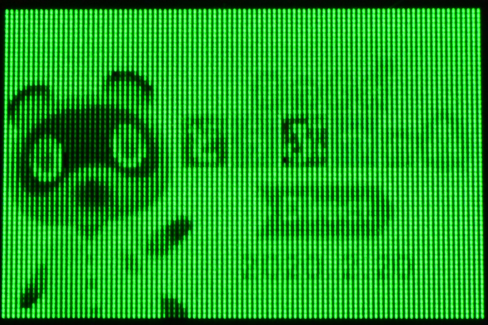
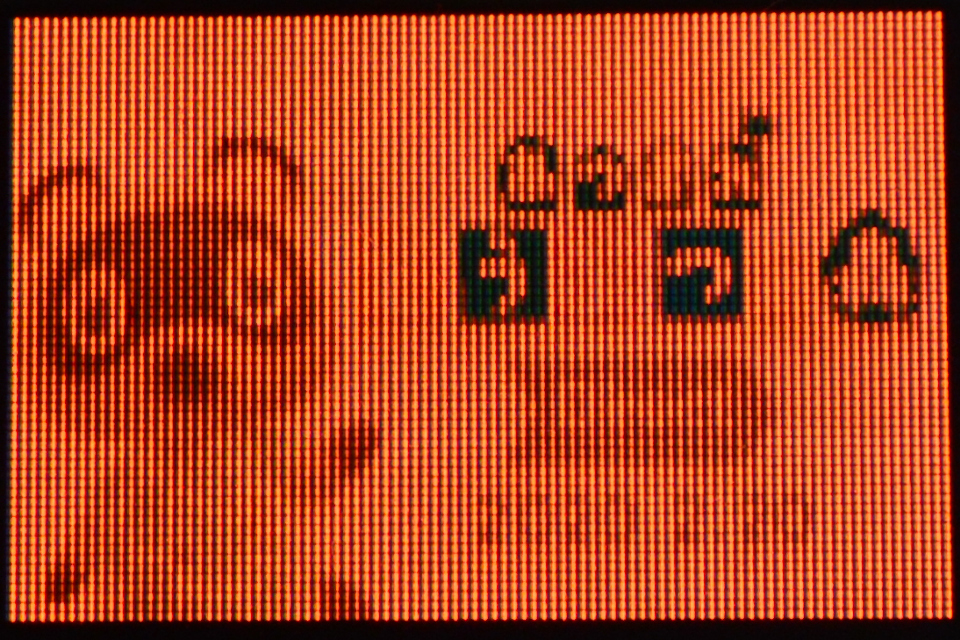
各色のコントラスト設定
- 0x81 : Set Contrast for Color "A"
- 0x82 : Set Contrast for Color "B"
- 0x83 : Set Contrast for Color "C"
wd[0] = 0x81;
wd[1] = 255;  // A Contrast 0-255
wd[2] = 0x82;
wd[3] = 0;    // B Contrast 0-255
wd[4] = 0x83;
wd[5] = 0;    // C Contrast 0-255
wiringPiSPIDataRW(SPI_CHANNEL, wd, 6);
wd[0] = 0x81;
wd[1] = 0;    // A Contrast 0-255
wd[2] = 0x82;
wd[3] = 255;  // B Contrast 0-255
wd[4] = 0x83;
wd[5] = 0;    // C Contrast 0-255
wiringPiSPIDataRW(SPI_CHANNEL, wd, 6);
wd[0] = 0x81;
wd[1] = 0;    // A Contrast 0-255
wd[2] = 0x82;
wd[3] = 0;    // B Contrast 0-255
wd[4] = 0x83;
wd[5] = 255;  // C Contrast 0-255
wiringPiSPIDataRW(SPI_CHANNEL, wd, 6);
パネルに供給する電流値の設定
- 0x87 : Master Current Control
// 値が小さいほど暗くなる
wd[0] = 0x87;
wd[1] = 0;  // 0-15
wiringPiSPIDataRW(SPI_CHANNEL, wd, 2);
表示モード
- 0xa4 ~ 0xa7 : Set Display Mode
0xa4 : 通常表示
0xa5 : 全表示
wd[0] = 0xa5;
wiringPiSPIDataRW(SPI_CHANNEL, wd, 1);
wd[0] = 0xa7;
wiringPiSPIDataRW(SPI_CHANNEL, wd, 1);
調光モード設定
- 0xab : Dim Mode Setting
wd[0] = 0xab;
wd[1] = 0x00;  // Reserved
wd[2] = 10;    // A Contrast 0-255
wd[3] = 10;    // B Contrast 0-255
wd[4] = 10;    // C Contrast 0-255
wd[5] = 10;    // Precharge voltage setting 0-31
wiringPiSPIDataRW(SPI_CHANNEL, wd, 6);

wd[0] = 0xac;  // dim mode
wiringPiSPIDataRW(SPI_CHANNEL, wd, 1);
表示On/Off
- 0xac ~ 0xa7 : Set Display ON/OFF
0xac : Display ON in dim mode
0xae : Display OFF (sleep mode)
0xaf : Display ON in normal mode
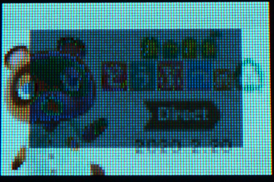
調光ウィンドウ設定(画面内の一部分のみ調光)
- 0x24 : Dim Window
wd[0] = 0x24;
wd[1] = 10;  // Column Address of Start 0-95
wd[2] = 10;  // Row Address of Start 0-63
wd[3] = 85;  // Column Address of End 0-95
wd[4] = 53;  // Row Address of End 0-63
wiringPiSPIDataRW(SPI_CHANNEL, wd, 5);
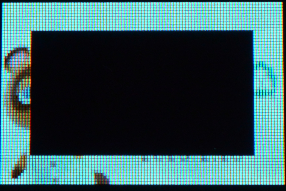
クリアウィンドウ設定(画面内の一部分のみクリア)
- 0x25 : Clear Window
wd[0] = 0x25;
wd[1] = 10;  // Column Address of Start 0-95
wd[2] = 10;  // Row Address of Start 0-63
wd[3] = 85;  // Column Address of End 0-95
wd[4] = 53;  // Row Address of End 0-63
wiringPiSPIDataRW(SPI_CHANNEL, wd, 5);
直線と四角形を表示するコマンドが予め用意されています。
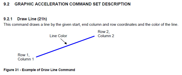
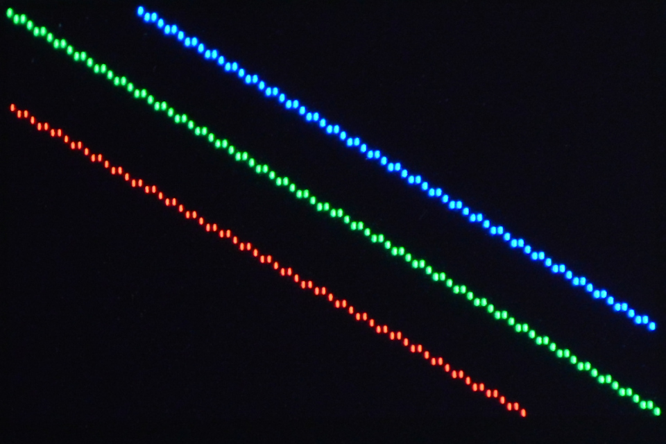
直線表示
- 0x21 : Draw Line
// 赤
wd[0] = 0x21;
wd[1] = 0;     // Column Address of Start 0-95
wd[2] = 15;    // Row Address of Start 0-63
wd[3] = 75;    // Column Address of End 0-95
wd[4] = 63;    // Row Address of End 0-63
wd[5] = 0x3e;  // Color C of the line 0x00-0x3e([0]=0)
wd[6] = 0x00;  // Color B of the line 0x00-0x3f
wd[7] = 0x00;  // Color A of the line 0x00-0x3e([0]=0)
wiringPiSPIDataRW(SPI_CHANNEL, wd, 8);

// 緑
wd[0] = 0x21;
wd[1] = 0;     // Column Address of Start 0-95
wd[2] = 0;     // Row Address of Start 0-63
wd[3] = 95;    // Column Address of End 0-95
wd[4] = 63;    // Row Address of End 0-63
wd[5] = 0x00;  // Color C of the line 0x00-0x3e([0]=0)
wd[6] = 0x3f;  // Color B of the line 0x00-0x3f
wd[7] = 0x00;  // Color A of the line 0x00-0x3e([0]=0)
wiringPiSPIDataRW(SPI_CHANNEL, wd, 8);

// 青
wd[0] = 0x21;
wd[1] = 20;    // Column Address of Start 0-95
wd[2] = 0;     // Row Address of Start 0-63
wd[3] = 95;    // Column Address of End 0-95
wd[4] = 50;    // Row Address of End 0-63
wd[5] = 0x00;  // Color C of the line 0x00-0x3e([0]=0)
wd[6] = 0x00;  // Color B of the line 0x00-0x3f
wd[7] = 0x3e;  // Color A of the line 0x00-0x3e([0]=0)
wiringPiSPIDataRW(SPI_CHANNEL, wd, 8);
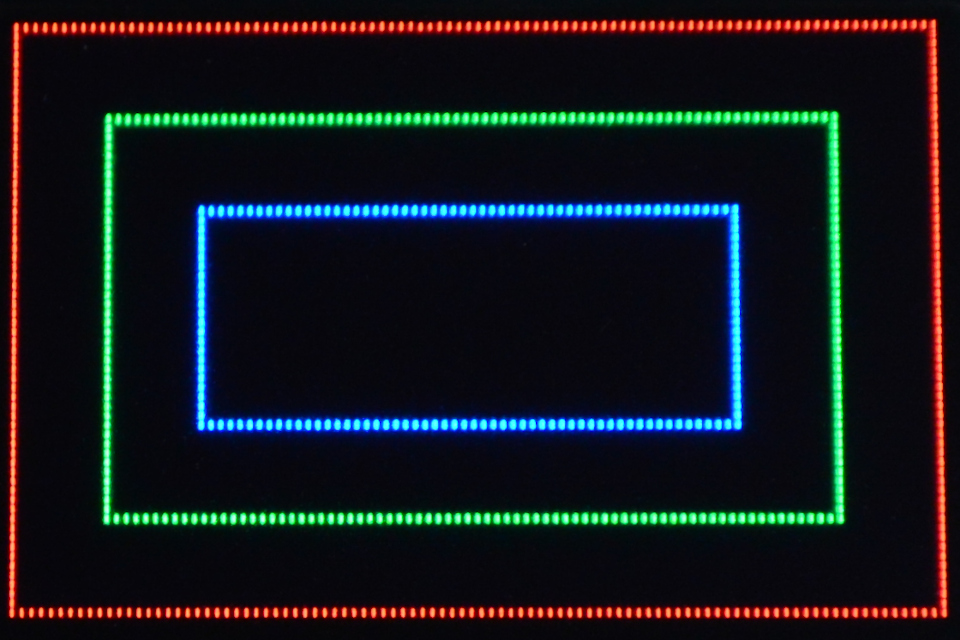
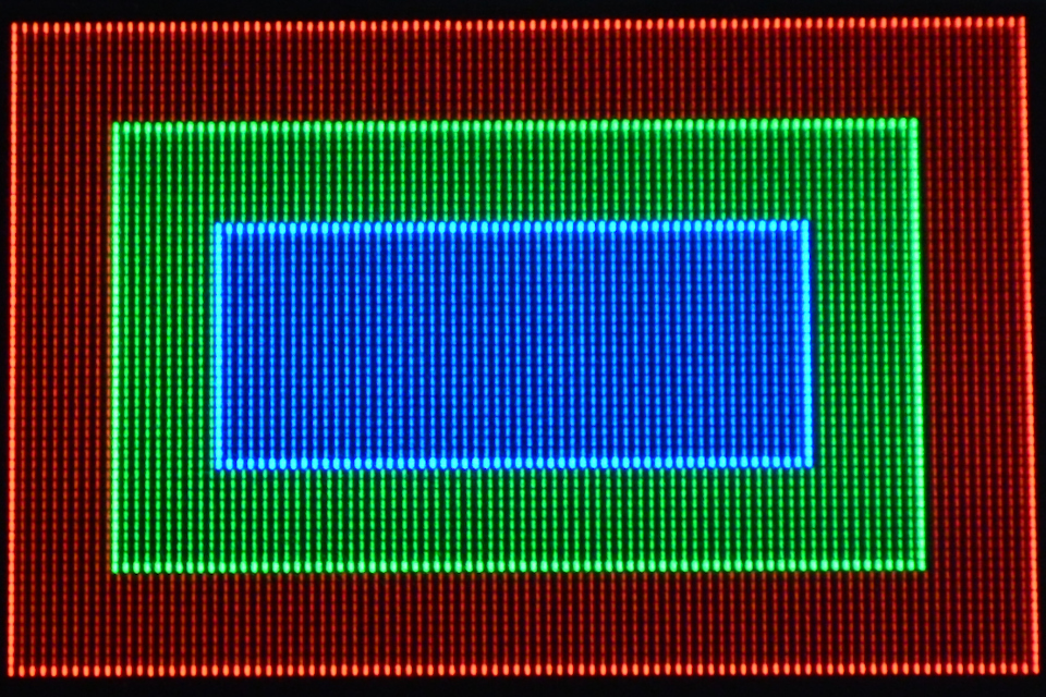
四角形表示と塗りつぶし
- 0x22 : Drawing Rectangle
- 0x26 : Fill Enable / Disable
// 塗りつぶし無し
wd[0] = 0x26;
wd[1] = 0x00;  // [4] = 0x0 : Disable reverse copy
               // [0] = 0x0 : Disable Fill for Draw Rectangle
wiringPiSPIDataRW(SPI_CHANNEL, wd, 2);

// 赤
wd[0]  = 0x22;
wd[1]  = 0;     // Column Address of Start 0-95
wd[2]  = 0;     // Row Address of Start 0-63
wd[3]  = 95;    // Column Address of End 0-95
wd[4]  = 63;    // Row Address of End 0-63
wd[5]  = 0x3e;  // Color C of the line 0x00-0x3e([0]=0)
wd[6]  = 0x00;  // Color B of the line 0x00-0x3f
wd[7]  = 0x00;  // Color A of the line 0x00-0x3e([0]=0)
wd[8]  = 0x00;  // Color C of the fill area 0x00-0x3e([0]=0)
wd[9]  = 0x00;  // Color B of the fill area 0x00-0x3f
wd[10] = 0x00;  // Color A of the fill area 0x00-0x3e([0]=0)
wiringPiSPIDataRW(SPI_CHANNEL, wd, 11);

// 緑
wd[0]  = 0x22;
wd[1]  = 10;    // Column Address of Start 0-95
wd[2]  = 10;    // Row Address of Start 0-63
wd[3]  = 85;    // Column Address of End 0-95
wd[4]  = 53;    // Row Address of End 0-63
wd[5]  = 0x00;  // Color C of the line 0x00-0x3e([0]=0)
wd[6]  = 0x3f;  // Color B of the line 0x00-0x3f
wd[7]  = 0x00;  // Color A of the line 0x00-0x3e([0]=0)
wd[8]  = 0x00;  // Color C of the fill area 0x00-0x3e([0]=0)
wd[9]  = 0x00;  // Color B of the fill area 0x00-0x3f
wd[10] = 0x00;  // Color A of the fill area 0x00-0x3e([0]=0)
wiringPiSPIDataRW(SPI_CHANNEL, wd, 11);

// 青
wd[0]  = 0x22;
wd[1]  = 20;    // Column Address of Start 0-95
wd[2]  = 20;    // Row Address of Start 0-63
wd[3]  = 75;    // Column Address of End 0-95
wd[4]  = 43;    // Row Address of End 0-63
wd[5]  = 0x00;  // Color C of the line 0x00-0x3e([0]=0)
wd[6]  = 0x00;  // Color B of the line 0x00-0x3f
wd[7]  = 0x3e;  // Color A of the line 0x00-0x3e([0]=0)
wd[8]  = 0x00;  // Color C of the fill area 0x00-0x3e([0]=0)
wd[9]  = 0x00;  // Color B of the fill area 0x00-0x3f
wd[10] = 0x00;  // Color A of the fill area 0x00-0x3e([0]=0)
wiringPiSPIDataRW(SPI_CHANNEL, wd, 11);
// 塗りつぶし有り
wd[0] = 0x26;
wd[1] = 0x01;  // [4] = 0x0 : Disable reverse copy
               // [0] = 0x1 : Enable Fill for Draw Rectangle
wiringPiSPIDataRW(SPI_CHANNEL, wd, 2);

// 赤
wd[0]  = 0x22;
wd[1]  = 0;     // Column Address of Start 0-95
wd[2]  = 0;     // Row Address of Start 0-63
wd[3]  = 95;    // Column Address of End 0-95
wd[4]  = 63;    // Row Address of End 0-63
wd[5]  = 0x3e;  // Color C of the line 0x00-0x3e([0]=0)
wd[6]  = 0x00;  // Color B of the line 0x00-0x3f
wd[7]  = 0x00;  // Color A of the line 0x00-0x3e([0]=0)
wd[8]  = 0x0e;  // Color C of the fill area 0x00-0x3e([0]=0)
wd[9]  = 0x00;  // Color B of the fill area 0x00-0x3f
wd[10] = 0x00;  // Color A of the fill area 0x00-0x3e([0]=0)
wiringPiSPIDataRW(SPI_CHANNEL, wd, 11);

// 緑
wd[0]  = 0x22;
wd[1]  = 10;    // Column Address of Start 0-95
wd[2]  = 10;    // Row Address of Start 0-63
wd[3]  = 85;    // Column Address of End 0-95
wd[4]  = 53;    // Row Address of End 0-63
wd[5]  = 0x00;  // Color C of the line 0x00-0x3e([0]=0)
wd[6]  = 0x3f;  // Color B of the line 0x00-0x3f
wd[7]  = 0x00;  // Color A of the line 0x00-0x3e([0]=0)
wd[8]  = 0x00;  // Color C of the fill area 0x00-0x3e([0]=0)
wd[9]  = 0x0f;  // Color B of the fill area 0x00-0x3f
wd[10] = 0x00;  // Color A of the fill area 0x00-0x3e([0]=0)
wiringPiSPIDataRW(SPI_CHANNEL, wd, 11);

// 青
wd[0]  = 0x22;
wd[1]  = 20;    // Column Address of Start 0-95
wd[2]  = 20;    // Row Address of Start 0-63
wd[3]  = 75;    // Column Address of End 0-95
wd[4]  = 43;    // Row Address of End 0-63
wd[5]  = 0x00;  // Color C of the line 0x00-0x3e([0]=0)
wd[6]  = 0x00;  // Color B of the line 0x00-0x3f
wd[7]  = 0x3e;  // Color A of the line 0x00-0x3e([0]=0)
wd[8]  = 0x00;  // Color C of the fill area 0x00-0x3e([0]=0)
wd[9]  = 0x00;  // Color B of the fill area 0x00-0x3f
wd[10] = 0x0e;  // Color A of the fill area 0x00-0x3e([0]=0)
wiringPiSPIDataRW(SPI_CHANNEL, wd, 11);
コピー
- 0x23 : Copy
// 通常コピー
wd[0] = 0x26;
wd[1] = 0x00;  // [4] : Disable reverse copy
               // [0] : Disable Fill for Draw Rectangle
wiringPiSPIDataRW(SPI_CHANNEL, wd, 2);

wd[0] = 0x23;
wd[1] = 0;   // Column Address of Start 0-95
wd[2] = 0;   // Row Address of Start 0-63
wd[3] = 40;  // Column Address of End 0-95
wd[4] = 40;  // Row Address of End 0-63
wd[5] = 50;  // Column Address of New Start 0-95
wd[6] = 15;  // Row Address of New Start 0-63
wiringPiSPIDataRW(SPI_CHANNEL, wd, 7);
// 色反転コピー
wd[0] = 0x26;
wd[1] = 0x10;  // [4] : Enable reverse during copy
               // [0] : Disable Fill for Draw Rectangle
wiringPiSPIDataRW(SPI_CHANNEL, wd, 2);

wd[0] = 0x23;
wd[1] = 0;   // Column Address of Start 0-95
wd[2] = 0;   // Row Address of Start 0-63
wd[3] = 40;  // Column Address of End 0-95
wd[4] = 40;  // Row Address of End 0-63
wd[5] = 50;  // Column Address of New Start 0-95
wd[6] = 15;  // Row Address of New Start 0-63
wiringPiSPIDataRW(SPI_CHANNEL, wd, 7);
スクロール設定
- 0x27 : Continuous Horizontal & Vertical Scrolling Setup
- 0x2e : Deactivate scrolling
- 0x2f : Activate scrolling
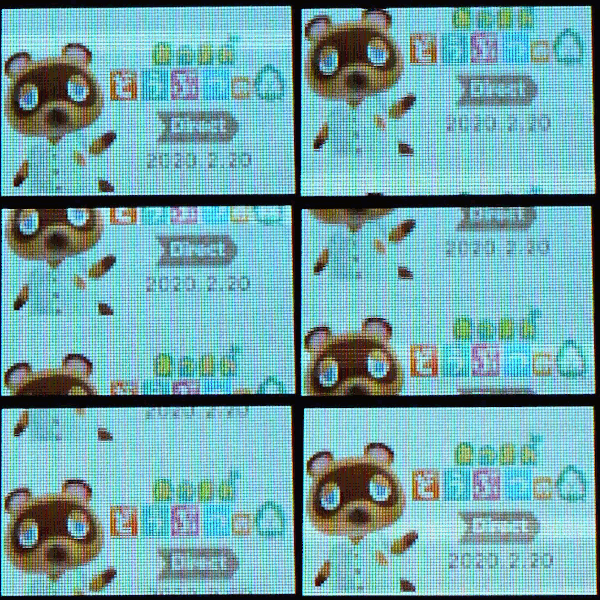
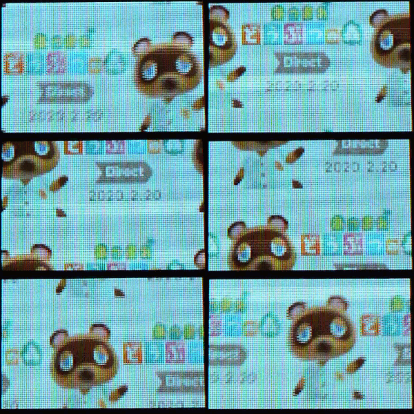
データシートに記載されているサンプル設定で動かしてみました。
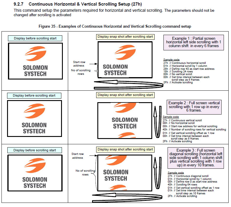
// Example 1
wd[0] = 0x27;
wd[1] = 0x01;  // Set number of column as horizontal scroll offset 0-95
wd[2] = 0x28;  // Define start row address 0-63
wd[3] = 0x18;  // Set number of rows to be horizontal scrolled 0-64
wd[4] = 0x00;  // Set number of row as vertical scroll offset0-63
wd[5] = 0x00;  // Set time interval between each scroll step 0-3
wiringPiSPIDataRW(SPI_CHANNEL, wd, 6);

wd[0] = 0x2f;  // Activate scrolling
wiringPiSPIDataRW(SPI_CHANNEL, wd, 1);

// Example 2
wd[0] = 0x27;
wd[1] = 0x00;  // Set number of column as horizontal scroll offset 0-95
wd[2] = 0x00;  // Define start row address 0-63
wd[3] = 0x40;  // Set number of rows to be horizontal scrolled 0-64
wd[4] = 0x01;  // Set number of row as vertical scroll offset0-63
wd[5] = 0x00;  // Set time interval between each scroll step 0-3
wiringPiSPIDataRW(SPI_CHANNEL, wd, 6);

wd[0] = 0x2f;  // Activate scrolling
wiringPiSPIDataRW(SPI_CHANNEL, wd, 1);
// Example 3
wd[0] = 0x27;
wd[1] = 0x01;  // Set number of column as horizontal scroll offset 0-95
wd[2] = 0x00;  // Define start row address 0-63
wd[3] = 0x40;  // Set number of rows to be horizontal scrolled 0-64
wd[4] = 0x01;  // Set number of row as vertical scroll offset0-63
wd[5] = 0x01;  // Set time interval between each scroll step 0-3
wiringPiSPIDataRW(SPI_CHANNEL, wd, 6);

wd[0] = 0x2f;  // Activate scrolling
wiringPiSPIDataRW(SPI_CHANNEL, wd, 1);
[参考記事]


